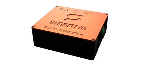
Relay module
16-channel mechanical relay expansion module with which lamps, shutters, a boiler, a garage door or almost any load can be switched from the Smartive system.
The module connects to the central unit through the extender port and contains dry-contact relays: the relay only switches; the switched circuit’s supply and protection are provided by the installation.
What it is for
Switching conventional and LED lighting circuits by room or by circuit.
Up/down direction of shutter motors, pulse-style control of a garage door.
Boiler enable contact, switching a pump or fan.
Any circuit that stays within the branch 10 A limit.
Technical data
| Characteristic | Value |
|---|---|
| Model / code / revision | Relay Module / SM-RELAY-EXP / Rev. 1.3 |
| Relays | 16 mechanical relays (HRS3FNH, 5 V coil), normally open contacts |
| Contact rating | Max. 10 A @ 250 VAC (per relay datasheet) |
| Installation limit | Max. 10 A @ 230 VAC per relay branch, with an external circuit breaker/fuse |
| Power supply | 5 VDC SELV; optional auxiliary 5 V/GND supply input (U1) |
| Control | MCP23017 I2C expander + relay driver transistors |
| Extender connector | 2 x RJ45 (daisy-chainable), pinout: SDA, 3.3V, 1-Wire, 5V, 5V, SCL, GND, GND |
| Insulation | Min. 5.5 mm insulation distance between the 230 VAC side and the control side |
| Surge protection | The module does not include a built-in SPD; if the installation requires it, it must be provided externally |
| Compliance | CE (LVD 2014/35/EU, EMC 2014/30/EU, RoHS 2011/65/EU) |
Auxiliary 5 V supply input (U1)
If many relays pull in at once, a voltage drop can occur on the 5 V arriving over the extender cable. For this case the module has a dedicated 5 V/GND supply-injection terminal block (U1).
- Only a CE-marked 5 V SELV power supply may be used, or another point of the same supply domain.
- Polarity and common GND must be checked before wiring.
- A power supply of a different voltage or one that is not isolated must not be connected.
Addressing
If several modules are connected to the central unit, each module must receive a unique address. Addressing is set with the 3-pin jumpers on the module: shorting the jumpers sets the binary address.
Setup in the app
- When adding a new device, select the GPIO Output option in the Device Model field.
- After selecting the I2C expander option, enter the port number on the module.
- Selecting the HIGH option tells the system to switch the relay on a high signal level.