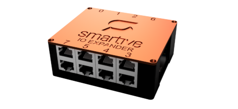
IO module
16-channel input expansion module for switches, motion sensors and other low-voltage signals.
The IO module adds the same kind of inputs to the system as the central unit’s own inputs — 16 more of them. The module works exclusively with SELV low-voltage signals; it contains no mains-voltage part.
What it is for
Wiring conventional (dumb) wall switches and push-buttons into the system.
Signals from motion and presence sensors with a low-voltage output.
Opening sensors, window contacts and other potential-free signal sources.
Tip: the central unit’s own inputs accept a signal of at most 3.3 V — the IO module inputs can be used up to 5 V.
Technical data
| Characteristic | Value |
|---|---|
| Model / code / revision | Input Module / SM-IO-EXP / Rev. 1.0 |
| Inputs | 16 digital inputs, on two 10-pole terminal blocks |
| Input signal level | Max. 5 V SELV (switches, motion sensors, contacts) |
| Power supply | 5 VDC SELV from the Smartive server/extender 5 V domain |
| Control | MCP23017 I2C expander for reading input states |
| Extender connector | 2 x RJ45, modules can be daisy-chained |
| Forbidden | 230 VAC, 24 V industrial signal, or any signal outside the 5 V SELV range |
| Compliance | CE (EMC 2014/30/EU, RoHS 2011/65/EU) |
Addressing
If several modules are connected to the central unit, each module must receive a unique address. Addressing is set with the 3-pin jumpers on the module.
Setup in the app
- When adding a new device, select the GPIO button option in the Device Model field.
- After selecting the I2C expander option, enter the port number on the module.
- If the other end of the switch is connected to GND, select the LOW option.