Commissioning
Commissioning is best started from a de-energized state: first the supply and protections, then the inputs, relay branches, network, and finally the expansion modules.
Checking the 5 VDC supply
The Smartive Server runs from a 5 VDC SELV supply. The device includes eFuse-based supply protection, which protects the control-side supply rail against reverse polarity, over- and undervoltage, current limiting and inrush transients.
Wiring the optocoupled input side
Field inputs couple to the control side through optocouplers. The optocoupled side has a dedicated isolated DC-DC supply, so the input side and the control side are galvanically isolated.
External protection of the relay branches
The server contains six mechanical dry-contact relay branches documented for 230 VAC switching. An external circuit breaker or fuse rated at no more than 10 A must be installed in front of every relay channel.
Network connection
Connect the LAN port to a router or switch. It is advisable to give the central unit a static IP in the router settings; the hostname defaults to smartive-core.
Addressing accessory modules
Modules connected on the extender port must be given a unique address. Two modules with the same jumper setting on the same bus can cause a communication collision.
Connecting the 5 VDC supply
The Smartive Server runs from a 5 VDC SELV supply. The device includes TPS259472 eFuse-based supply protection, which protects the MCU/Raspberry supply rail against reverse polarity, over- and undervoltage, current limiting and inrush transients.
Use only a CE-marked external power supply of adequate power. For the Raspberry Pi 4 variant at least 15 W is recommended; for a Raspberry Pi 5 variant used with a full peripheral frame, a 25 W power supply is recommended.
Connecting the optocoupled inputs
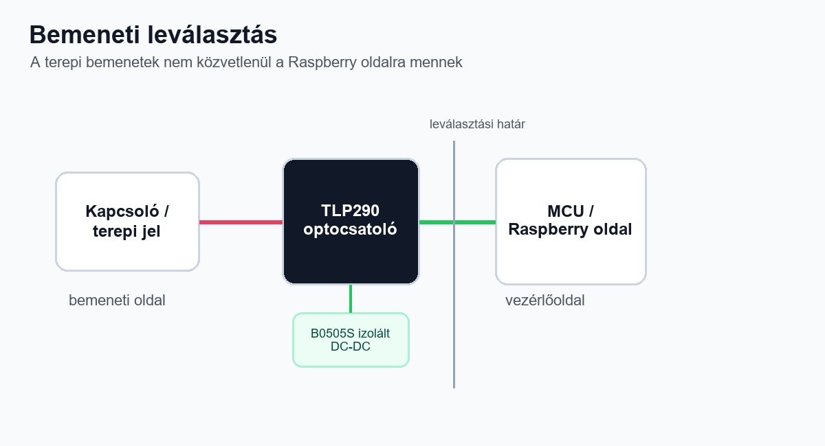
Field inputs couple to the control side through TLP290/TLP290-4 optocouplers. The optocoupled side has a dedicated B0505S-1WR3 isolated DC-DC converter, so the input side and the MCU/Raspberry side are galvanically isolated.
Wiring the 230 VAC relay branches
The server contains six mechanical dry-contact relay branches documented for 230 VAC switching. An external circuit breaker or fuse rated at no more than 10 A must be installed in front of every relay channel.
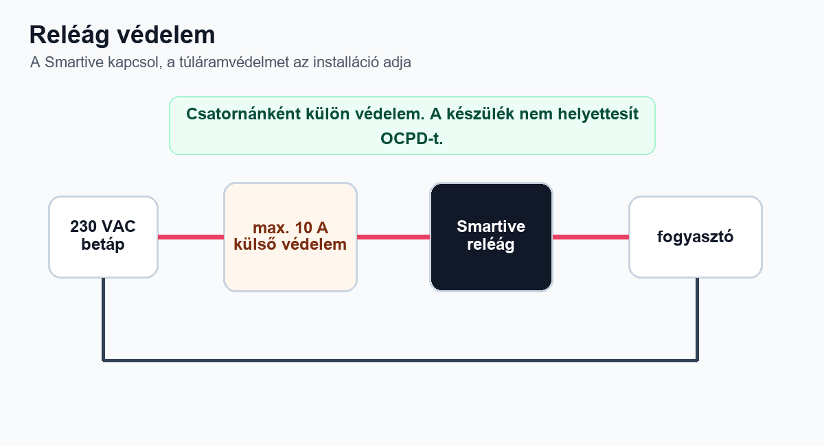
- Every relay channel has a dedicated external protection rated at no more than 10 A in front of it.
- The relay branches are mounted in a closed electrical or control cabinet.
- The 5 V supply and the external feed of the relay branches can also be disconnected separately before service.
Connecting the Ethernet cable
For the device to join the local network and the internet, connect the LAN port to the router or switch.
Assigning a static IP
It is advisable to give the central unit a static IP. Do this in the router settings. The central unit
hostname defaults to: smartive-core.
Connecting accessory modules
If you also connect accessory modules to the central unit through the extender port, for example a relay module, solid-state relay module or IO module, the modules must be given a unique address.
Setting the address
The physical address of the modules is set with the 3-pin jumpers on the board. Shorting the jumpers sets the binary address.
Never use two modules with the same jumper setting on the same bus, because this can lead to a collision and communication failure!