Central unit
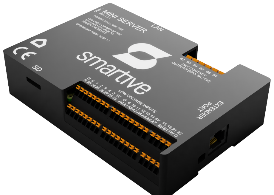
Central unit with 5 VDC supply, an isolated input side and 230 VAC relay branches.
This document is a quick mounting and usage overview of the Smartive Server SM-MS central unit. This server is a variant documented for 230 VAC relay branches.
The main new features: eFuse supply protection, optocoupled and galvanically isolated inputs, a dedicated input-side DC-DC supply, and six 230 VAC dry-contact relay branches.
What it can be used for
You can connect to the central unit:
They connect to the control side through the optocoupled input side.
Digital sensors and 1-Wire thermometers for local automations.
Circuits switched on 230 VAC relay branches, with appropriate external protection.
Additional IO, relay or other Smartive modules through the extender port.
The system is designed for star-topology cabling: inputs and outputs run back to the central unit or to a connected expander module. The Smartive system then decides which output to switch on an event such as a button press, motion or an automation.
Technical data
| Characteristic | Value |
|---|---|
| Model / revision | SM-MS / Rev. 1.3.0 |
| Base system | Raspberry Pi 4 Model B or Raspberry Pi 5 (depending on variant) |
| Power supply | 5 VDC SELV; Pi 4: min. 15 W, Pi 5 with full peripheral frame: 25 W |
| Supply protection | eFuse: reverse polarity, over-/undervoltage, current limiting, inrush transient |
| Inputs | Optocoupled, galvanically isolated field inputs, with a dedicated isolated supply rail |
| Relay outputs | 6 mechanical dry-contact relay branches; max. 10 A @ 230 VAC / channel, with external protection |
| Network and ports | Ethernet, 2 x USB 2.0, 2 x USB 3.0, 2 x Micro-HDMI |
| Radio | Wi-Fi 5, Bluetooth Low Energy 5.0 |
| Sensors | Built-in temperature and humidity sensor; 1-Wire port for external thermometers |
| Expansion | RJ45 extender port for Smartive modules |
| Physical size | 133 x 92 x 29 mm |
| Mounting | DIN rail, in a closed electrical or control cabinet |
| Firmware | Smartive firmware, with digitally signed OTA updates |
| Compliance | CE (RED 2014/53/EU, RoHS 2011/65/EU) |
Accessing the central unit and the app connection
After installing the Smartive app, you need to pair the app with the central unit. This can be done in two ways:
Pairs the app with the unit on the local network. In this mode the system cannot be reached remotely.
Provides a connection reachable from anywhere, but requires creating a Smartive Cloud account.
The Smartive application running on the central unit can be reached locally at the following URL:
https://smartive-core.local:64539
or http://smartive-core.local:64538
Contents
Physical connectors, port logic and safety limits.
First checks of the supply, network, inputs and relay branches.
Wiring direction for switches and field inputs.
Connecting a motion sensor and adding it in the app.
Wiring and identifying the thermometer bus.
Wiring conditions for relay branches and external protection.
SD card replacement and system boot.
Common faults, checkpoints and recovery.