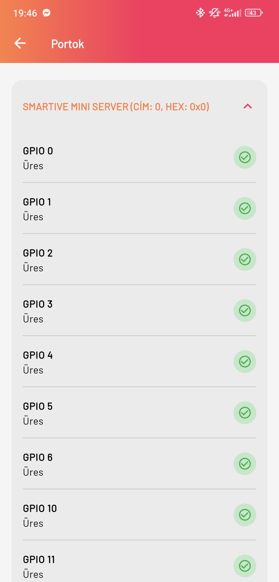
Ports
At the ports, physical location matters, but so does which electrical side each connector represents. The inputs are isolated, and the relay branches may only be used with appropriate external protection.
The Smartive Server central unit port layout includes protections that matter for safety. The input side is optocoupled and galvanically isolated, and the relay branches are documented for 230 VAC switching.
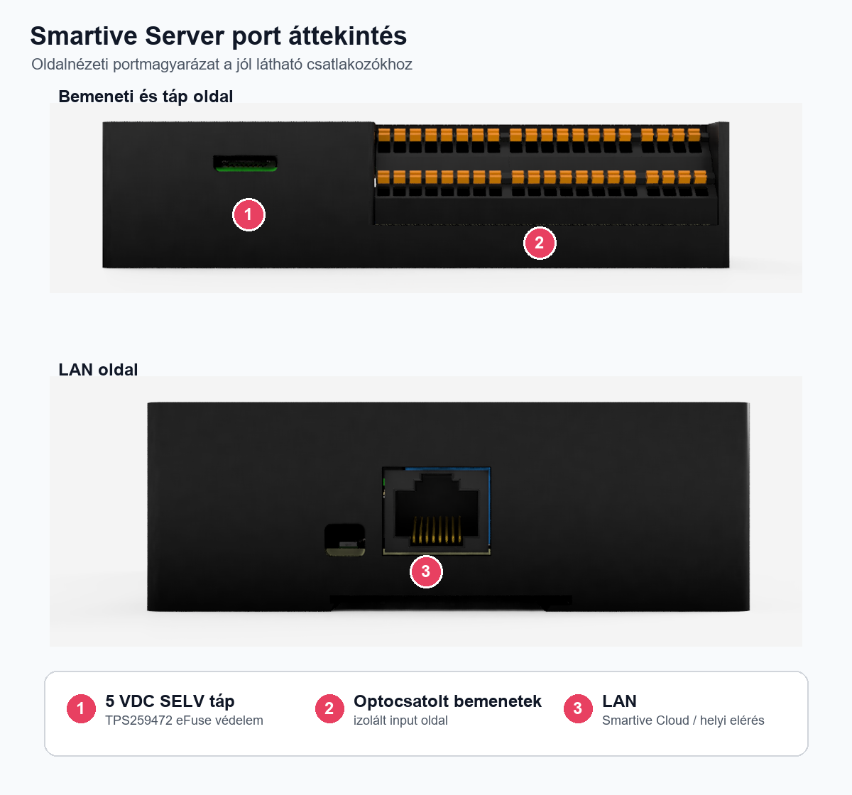
Port logic: separately protected 5 VDC supply, optocoupled input side and 230 VAC relay branches.
- The 5 VDC supply comes only from a SELV power supply.
- The input-side and control-side potential boundaries are not tied together.
- The 230 VAC relay branches have their own external protection per channel.
- Modules connected on the extender port receive a unique address.
| Port | Role | Note |
|---|---|---|
| 5 VDC | Power supply | SELV power supply, with TPS259472 eFuse protection inside the device. |
| LAN | Network connection | Required for local access and the Smartive Cloud connection. |
| Optocoupled inputs | Switches, field input signals | A dedicated isolated DC-DC supply separates the input side from the MCU/Raspberry side. |
| 6 x dry-contact relay branch | Switching 230 VAC loads | Max. 10 A @ 230 VAC/channel, with a mandatory external circuit breaker or fuse. |
| Extender port | Expansion modules | For connecting IO, relay or other Smartive expansion modules. |
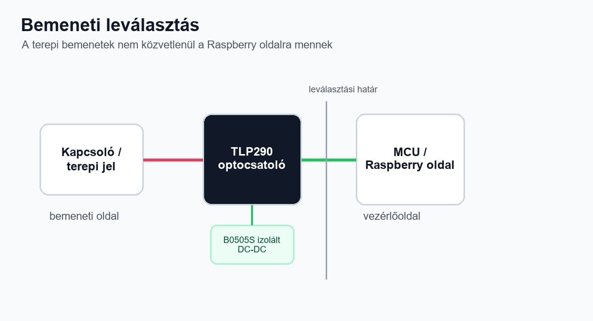
The input side is galvanically isolated: the field signal reaches the control side through an optocoupler.
The 230 VAC relay branches may only be used in a closed electrical or control cabinet, installed by a qualified person. The per-channel
max. 10 A external protection is not a recommendation, but an installation requirement.
Ports in the app
In the app, pressing the FTP button in the top-right corner of the Current mini server
submenu of Settings shows the list of ports. You can see which ports
are available and which device is wired to each one.